File Menu
At the top is the GUI is the File menu, which is generally self-explanatory; however, note that the Convert All Airfoils to Latest Format command is a batch command. If you execute this command, then Airfoil Maker will traverse the entire X-Plane folder, converting every airfoil file it finds to the latest file format. With older *.afl file formats, you could only have coefficient curves for one Reynolds number per *.afl file, whereas in the latest file format, you can now have multiple curve sets for multiple Reynolds numbers in one *.afl file.
General Layout
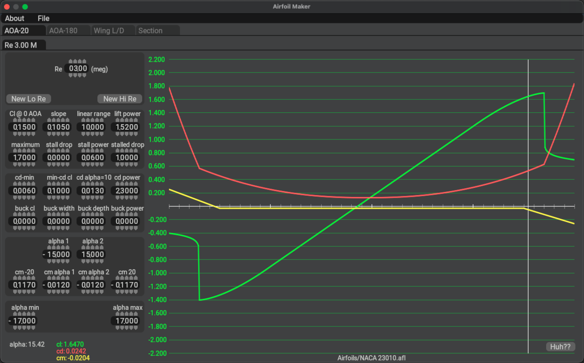
The next image below shows the general window layout when configuring the coefficient curves. The AOA-20 tab is shown active and is typically the only tab you need to make edits on. The other 3 tabs and their views are discussed further below.
The left side of the GUI have four logical data sections, highlighted with magenta bars below. The logical sections are:
- Active Reynolds Number: This is the Reynolds Number value for the active set of coefficient curves displayed.
- Curve Parameter Entry: These are the widgets for entering equation parameters to shape the coefficient curves.
- Max/Min Stall AoA/alpha: These are the max/min AoA values at which the max/min \(C_l\) is achieved.
- AoA / Coefficient Pairs: These are the curve data pairs (Alpha, coefficient) under the AoA Cursor (white vertical bar). They are used to examine coefficient values at various Alpha points along the curve. They will change as you move the AoA cursor around the graph. Move the cursor to the Alpha angle you want and use these to examine the coefficients at that Alpha value.
The right side of the GUI simply shows the resulting coefficient graphs calculated from the parameters entered. The coefficient range is displayed on the vertical axis and the AoA values are on the horizontal axis, though you need to move the AoA cursor left/right and read the Alpha (AoA) value from the Feedback values at the lower left.
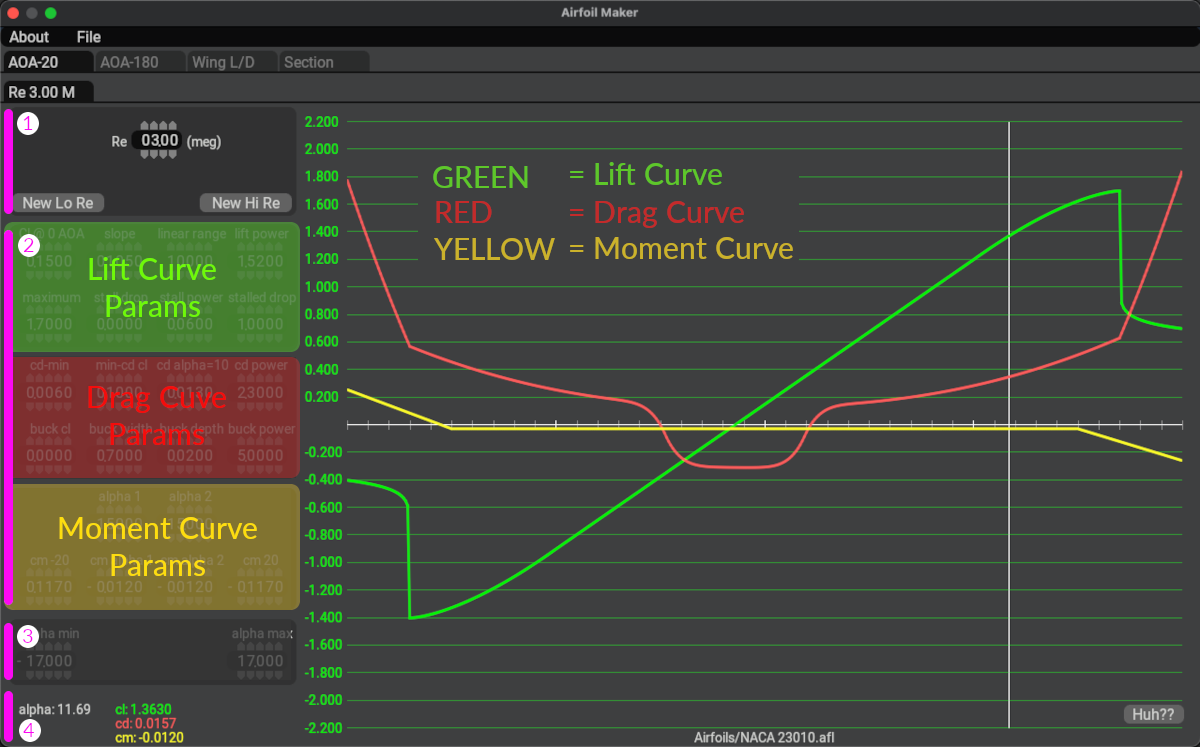
AOA-20 Tab
The AOA-20 tab is the primary tab on which you enter all the coefficient curve parameters and Reynolds numbers. Most of the time, this is the only tab you need to see and use. It displays the coefficient graphs within the range of AoAs between -20º and 20º. As you adjust the parameters at left, the graphs will be updated in real time. See the Lift / Drag / Moment Curves section of this manual for configuring each curve type.
![]() See Austin's AoA-20 Tutorial Video for additional information about this tab.
See Austin's AoA-20 Tutorial Video for additional information about this tab.
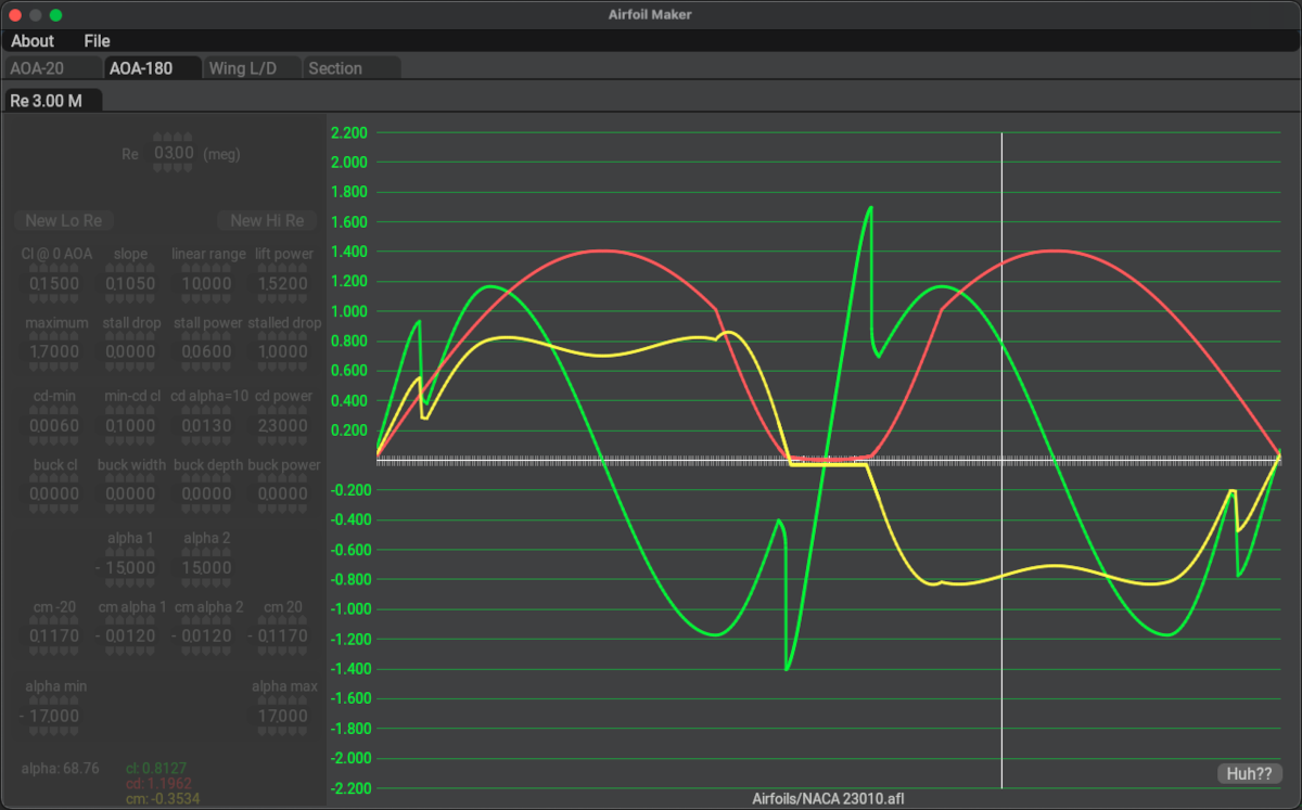
AOA-180 Tab
The AOA-180 Tab displays coefficient curve graphs for alpha values from -180º to +180º. The graphs are extrapolated beyond the min/max Alpha values algorithmically and you cannot adjust the data points outside the min/max Alpha explicitly. This view/tab graph is not utilized much, if it all, for conventional aircraft, but could be useful if one were modeling control algorithms for attitude control, such as is done on the Space-X rockets, where you need to know the coefficients beyond the stall alphas for feedback. You can configure the curve parameters while on this tab, they are the same as on the AOA-20 tab.
![]() See Austin's AoA-180 Tutorial Video for additional information about this tab.
See Austin's AoA-180 Tutorial Video for additional information about this tab.
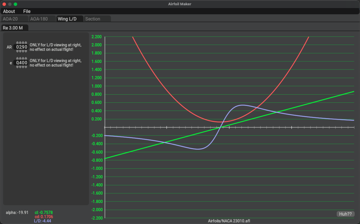
Wing L/D Tab
The Wing L/D tab is informational only. It is useful to check the results of your entries by calculating the L/D (lift over drag ratio) for a finite wingspan. The 2D airfoil coefficients on the previous tabs are not achieved in real life because they are based on a hypothetical wing of infinite wingspan. In reality, downwash and wingtip vorticies on finite wingspans rob the airflow of its lifting potential, increasing drag and thereby reducing the total Wing Coefficients relative to the "infinite wing case" 2D Airfoil Section coefficients.
Enter the aspect ratio (AR) for your wing and the efficiency factor e. These parameters are the inputs to an approximation equation to estimate the overall Wing lift and drag characteristics resulting from a finite wingspan.
A glider or U–2 Dragon Lady with extremely long wings might have an aspect ratio of 30. A light aircraft such as a Cessna 180 has an aspect ratio of 7.3. The aspect ratio of a straight wing is the wingspan divided by the chord. For any other shape of wing, the easiest way to calculate AR is to square the wing span and divide by the wing area like so:
![]() See Austin's Wing L/D Tutorial Video for additional information about this tab.
See Austin's Wing L/D Tutorial Video for additional information about this tab.
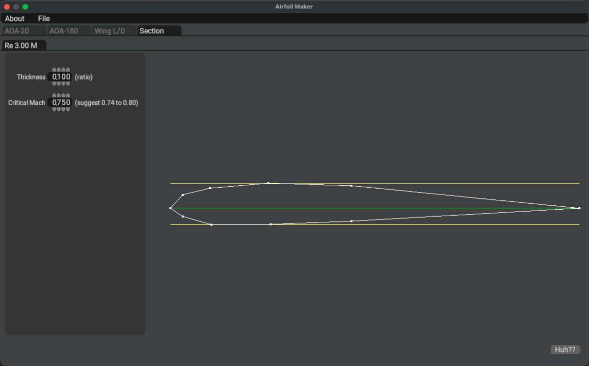
Section Tab
The section tab is used to define the section profile. This graphic profile is ONLY used for the 3D model of the PlaneMaker wing and has absolutely NO BEARING on the aerodynamics of the wing. If you are hiding the PlaneMaker wings in PlaneMaker, then the visual 2D profile is irrelevant.
IF you are modeling a supersonic aircraft however, then you DO want to enter the thickness value, as X-Plane uses that value to estimate supersonic drag. You also want to enter the critical Mach numbers, as this tells X-Plane WHEN to begin applying supersonic drag. The Critical mach number is a function of the airfoil design.
![]() See Austin's Section Tutorial Video for additional information about this tab.
See Austin's Section Tutorial Video for additional information about this tab.