Shaping Drag Curves
NOTE
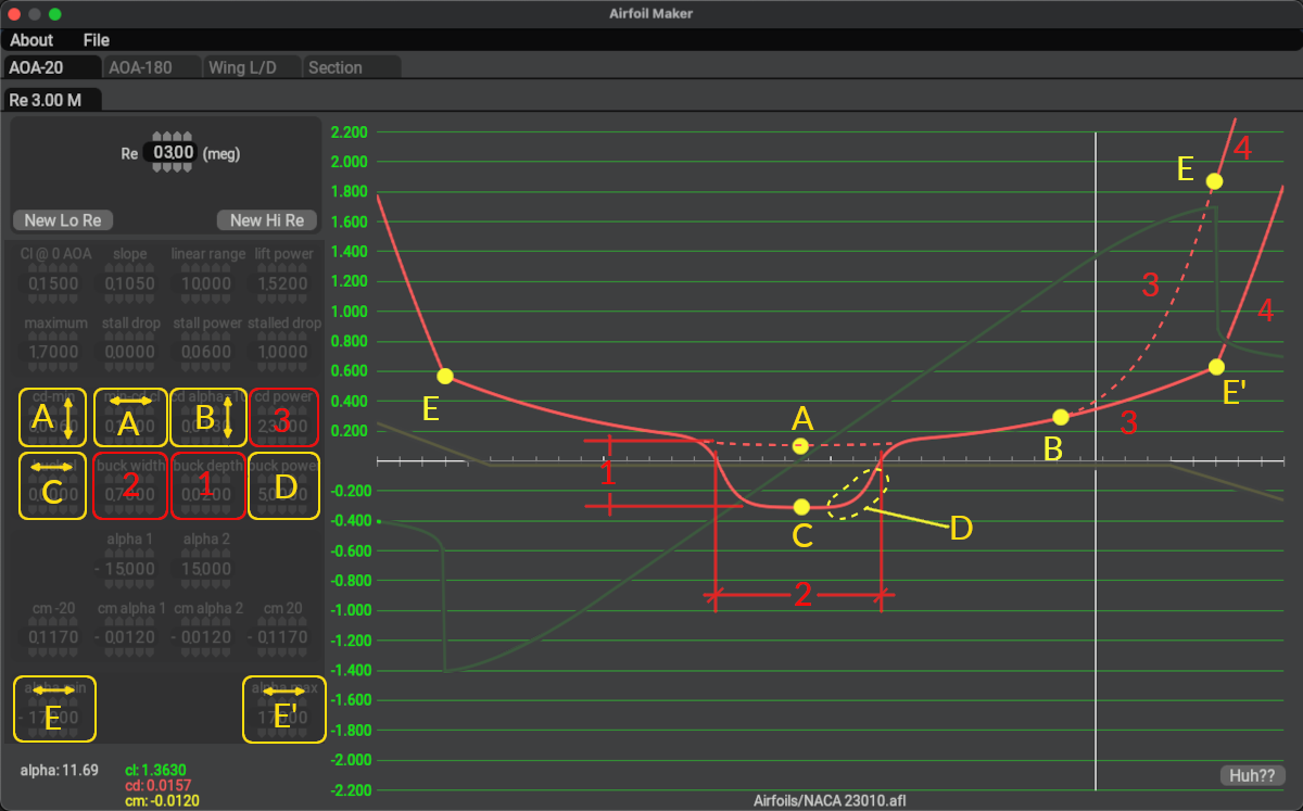
The image below contains overlay labels and highlights for clarification and learning purposes in this manual. Airfoil Maker does not contain such labels and colors on its GUI. You can hover over the widgets in the image below for tooltips on the various widget functions.
Drag curves are assembled from a slightly more complex combination of equations than the lift curves, and usually require a bit more trial and error to shape. Some drag curves for Laminar Flow Airfoils have what is called a Laminar Drag Bucket, which is a region of low drag at low Alpha values. The drag curve in this region resembles a bucket and is illustrated below (point C), hence the name. Non-Laminar flow airfoils do not generally exhibit such a drag bucket and their drag curves are more of a U-shape.
The parameters to configure the drag curve are contained primarily in two rows of widgets as highlighted below. The bottom row is used to configure laminar buckets; therefore, if your foil have no Laminar bucket region, then the entire 2nd row of parameters can be zero and you only need to configure the top four widgets to shape your drag curve. The widgets overlayed in yellow below will move curve points around and the widgets overlayed in red will alter the shape/distance of segments between the indicated points. These points are NOT shown in the AirfoilMaker GUI.
For example, changing parameter A, the Alpha value at which minimum drag is achieved (ignoring the bucket) will cause point A to shift up or down. Increasing the cd power parameter will bend segment 3 upwards from point B (dashed line), pushing point E and segment 4 upwards. You can hover over the widgets below to get more information on how each parameter shapes the drag curve.